It has been forty years since the Reader's Digest Magazine published this digest of a New York Times article from August of 1980. That summer, at the International Human Powered Speed Championships, a streamlined tandem tricycle, the Vector, was the first human-powered vehicle to break the 60mph barrier for a flying 200m speed run. But what captured the media's attention was that same tandem trike was pedaled from Stockton to Sacramento California on Highway 5 covering 41.8 miles at an average speed of 50.5 mph. Finally, it seemed that streamlined human-powered vehicles could provide a viable, healthy alternatives to the automobile.
In this vein, the magazine article described a hypothetical future commute to work by "Joe Wheeler", pedaling a single-person, Vector-like velomobile, the Shooting Star. Joe, riding along dedicated human-powered-vehicle lanes, covers 25 miles at an average speed of 60mph.
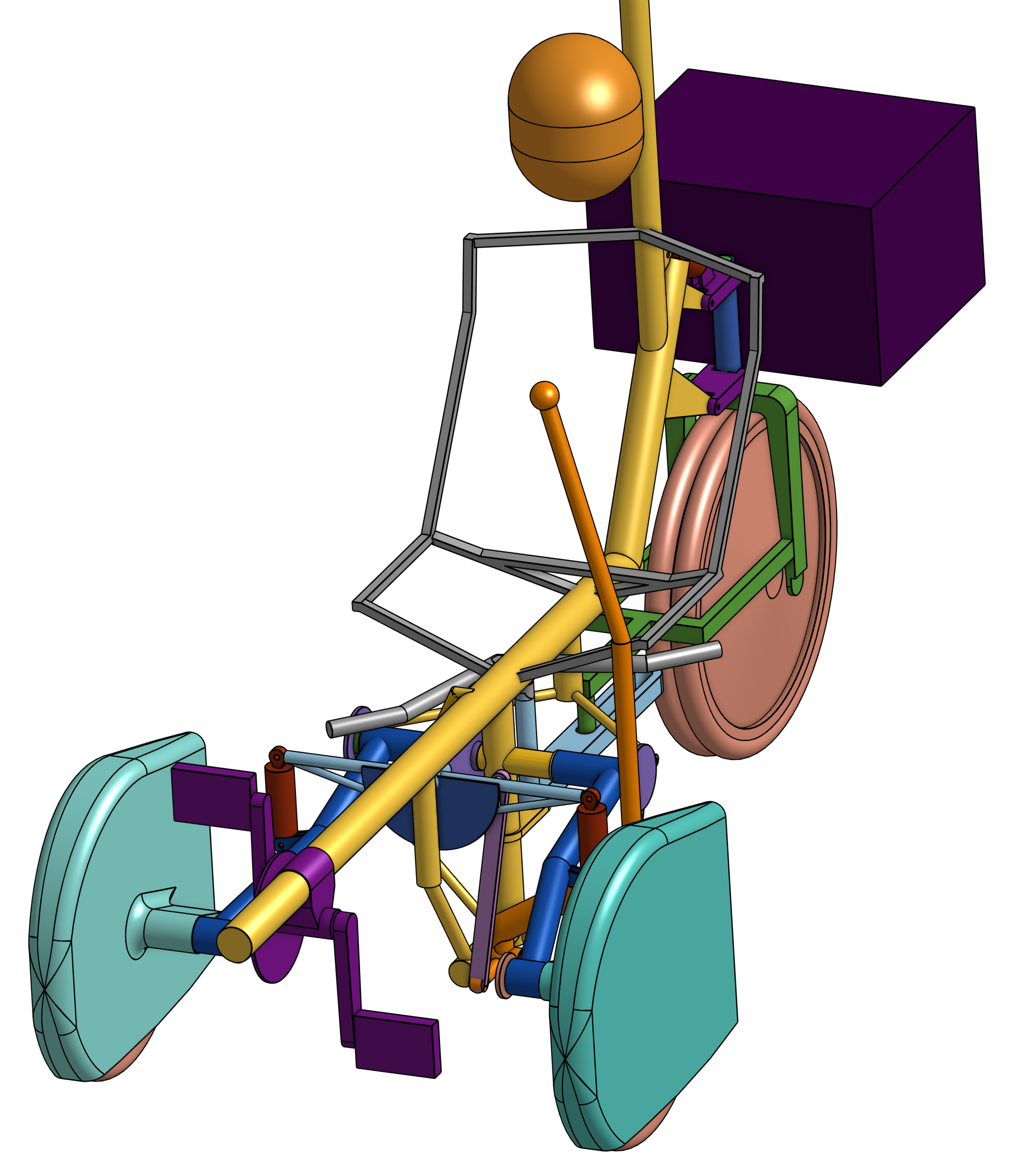
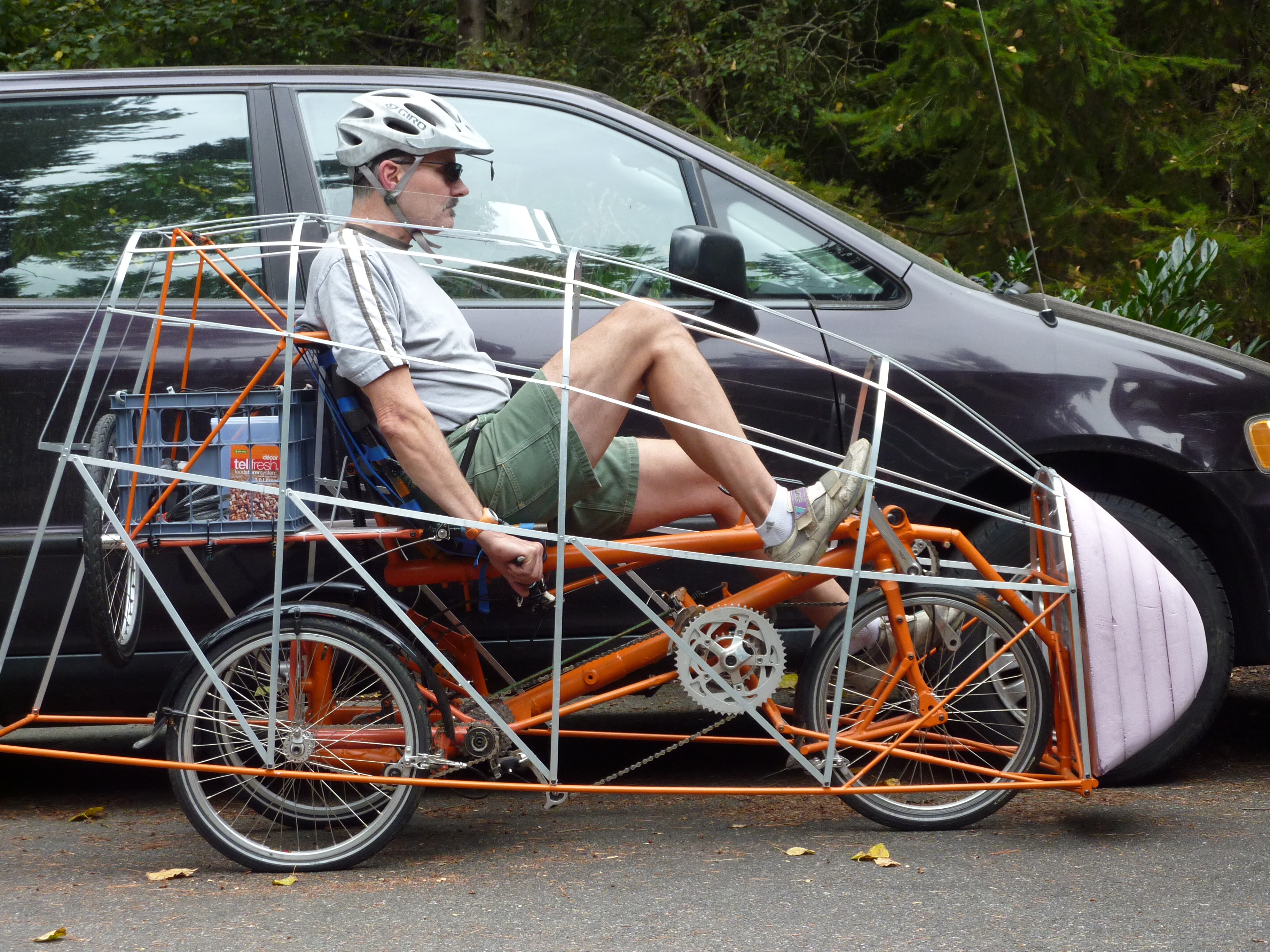
The article goes on to show a schematic of the single-person Vector.
And I have added a close-up photo of the Vector's interior. Note that the width of the Vector is 25in. and the height is 32in.
So 40 years has passed and why aren't people zipping to work in bullet shaped tricycles? One answer is transportation infrastructure. There are no limited-access high-speed bike paths for vehicles like the Vector. I do occasionally see a bright-yellow Quest velomobile on the local bike way, but I have never seen it in the bike lanes adjacent to local roads.
Now the progression in HPV speeds has continued in the ensuing 40 years. The longest distance covered in an hour is 58 miles and the flying 200m record is almost 90mph. The current trend has been to use a two-wheel layout since the aerodynamics are significantly better than three and four wheel designs.
The Vector trikes, like the dragsters of the automotive world, were limited-use vehicles. The same small cross-section that made them so aerodynamic also made them very difficult to see from the perspective of an automotive driver. During its record setting 42 mile highway run, the Vector tandem was bracketed, front and back, by guard vehicles to protect it from autos merging into the space it occupied. The limited wheel lock for the steered front wheels made only large radius turns possible. The lightweight high-pressure tires required a clean road surface to prevent punctures. And the rider in the Vector had a limited field of view. Not to mention that a light 51 lb. vehicle provides woefully inadequate crash protection for a vehicle traveling at 60mph. Finally, these low-narrow layouts require the assistance of at least another person for the rider to get in and out of the vehicle
Now, after the Vector speed records, Alan Carpenter, a designer from Colorado, build a production vehicle that he felt would be a practical human-powered vehicle. The Cyclodyne was a very well thought out and well-engineered vehicle.
The Cyclodyne was a tadpole trike, like the Vector. It was, however higher at 40in. for better visibility and wider at 38in. to provide the necessary roll-over resistance. It even incorporated driven front wheels to double the drive traction over the typical tadpole trike. A fit cyclist could pedal the Cyclodyne at over 30mph.
One owner related a critical problem with the Cyclodyne. Even being pedaled at 35mph, it was not fast enough to prevent traffic backups behind it when ridden in automobile lanes. The motorists didn't know what to make of the vehicle. In frustration, he finally removed the faring so the drivers could see he was operating only on pedal power. His speed fell drastically, but the cars lost their reluctance to pass him and the backups were eliminated.
Since the Cyclodyne was only 38in. wide, it would comfortably fit within most bike lanes located adjacent to many roadways but it was not fast enough to be interleaved with automobiles. The appropriate traffic infrastructure wasn't available for the above owner.
The Cyclodyne demonstrates that, with a bit more attention paid to aerodynamics, an enclosed all-weather trike could reasonably be expected to have a top speed of over 40mph.
So back to transportation infrastructure. Where could such a vehicle be ridden? Do legal vehicle speeds preclude the use of such vehicles?
A catalog of the places and speed limits for use in the Seattle, Washington reads something like this:
Sidewalks, no speed limits
Residential streets, 25mph
Local roads, 35 to 40mph. Most of these roads have adjacent bike lanes.
Interstate highways. 60mph in the city and 70mph outside the city. Many of the highways outside the city have wide shoulders that allow cyclists to safely use them.
So residential streets and any other roads with adjacent bike lanes would be acceptable. For safety reasons there are the two requirements that the vehicle should be clearly visible to motorists and narrow enough to not obstruct traffic. A Cyclodyne-like vehicle satisfies these requirements.
Carpenter made one bad decision that limited the sales of the Cyclodyne. Its price tag of $4000 in 1980's dollars. He justification was that Early Winters, an outdoor outfitter in Seattle, was selling a used Vector trike for $10,000. Now the the Vector cost was not representative of a production vehicle. There was only one of them and it never sold. It ultimately was donated to a Seattle human-powered vehicle club.
Let us assume that a Cyclodyne-like tadpole trike, with some aerodynamic improvements would allow a reasonably fit rider to reach 40mph without sprinting. So the technology predicted in the Reader's Digest article exists, albeit at a 40mph level instead of a 60mph level.
(In fact, since the Cyclodyne already had front-wheel drive, one big improvement would be to allow the rear wheel to do the steering. The front wheels would present less frontal area. The main faring could just enclose the rider and the rear-steered wheel. The front wheels could be mounted outside the faring with individual wheel pants to streamline them. Joy-stick steering could be substituted for the under-seat steering to further reduce the faring width. While the drag coefficient for this layout might be greater that the original design, the cross-sectional area would be significantly reduced and the product of drag coefficient and cross-sectional area would make the vehicle more aerodynamic. This would be at the expense of some cargo capacity. In addition, having two front wheels that do not steer is much more stable when going over obstacles when compared to two steered wheels which can be deflected causing unwanted steering inputs.)

The continued development or an all-weather commuter vehicle that could be safely integrated with traffic has also been largely curtailed by pedal-electric technology.
But is the electrification of bicycles and tricycles a bad thing for the development of human-powered commuter vehicles?
Let's look at the electric bicycle regulations for Washington state to get more specific on answering that question. Keeping in mind that tricycles and velomobiles fall under these requirements.
The above regulation lost part of a sentence, one that is as important as the categories. The second sentence should read "The electric bike must have two or three wheels and fully functioning pedals" .
The eliminates vehicles like the Pod Bike (strange name for a four-wheel vehicle) and the Quattro Velo if it includes electrification. Now this is a bad requirement if one is designing an all-weather commuter vehicle, since for a given track and weight distribution, a quad had 50% more rollover resistance than a trike. On the other hand, a four-wheel motorized vehicle falls into the category of a micro car with all of its extra regulations.
Another electric bike regulation says that the vehicle must have a bicycle seat and for trikes, one of the wheels must be at least 20" in diameter. Now requiring a bike seat would eliminate all recumbents. And I, like the Cyclodyne designer, prefer three 16" wheels because they allow a smaller vehicle volume.
Class 3 is a recent and welcome addition to what is considered an pedal-electric vehicle.
Now a fit cyclist can generate 200+ Watts of mechanical power. So with more than three times the available power, aerodynamic and weight considerations can essentially be ignored. One problem that this surplus power can't solve is vehicle width.
For visibility in traffic, it is desirable that the rider's head height is no lower that that of a driver in a sports car. For static tricycles, roll-over-resistance is developed by making the vehicle width approximately on the order of twice the height of the vehicles center-of-gravity, c.g. If the designer is not diligent in keeping the c.g. low, the vehicle width can get excessive. It is my opinion that electric velomobiles like the Elf, with a 48" width, are too wide to share dedicated bike lanes with other vehicles.
I think that electric velomobiles should have a width restriction of 1m (39") for access to dedicated and roadway adjacent bike lanes.
An electrified version of the Cyclodyne, at a 38" width, could easily manage the 28mph speed limit for a Class 3 electric tricycle and be a very beneficial all-weather pedal-electric commuter vehicle.
Hephaestus


.jpg)